Multiple Spanning Tree Protocol (MSTP) maps groups of VLANs to a small number of spanning tree instances. You get RSTP-speed convergence, per-instance load balancing, and a fraction of the CPU overhead that PVST+ burns through at scale.
If your network has 100+ VLANs running PVST+, you’ve got 100+ concurrent STP instances on every switch. MSTP cuts that down to a handful. That’s the point.
Defined in IEEE 802.1s (2002) and later absorbed into IEEE 802.1Q-2014, MSTP is the standard choice for large enterprise campuses, data centres, and multi-vendor environments. This guide covers how it works, why it exists, how it compares to RSTP and PVST+, and how to configure it on Cisco IOS with real commands.
Quick answer for busy engineers: MSTP (IEEE 802.1s, now part of 802.1Q-2005) lets you assign dozens of VLANs to a single MST instance. Each instance builds its own spanning tree. You get per-instance root bridges, per-instance load balancing, and RSTP-speed convergence – all while running only 2 to 4 active instances on big networks.
What Is the Multiple Spanning Tree Protocol?
Multiple Spanning Tree Protocol is an IEEE standard that groups VLANs into spanning tree instances. Each instance runs its own independent RSTP-based topology.
Here’s what that looks like in numbers:
- 200 VLANs on PVST+ = 200 STP instances running simultaneously on every switch
- 200 VLANs on MSTP = 5 to 10 instances, each covering groups of VLANs
That difference matters. On a core switch with 200 VLANs, PVST+ sends 200 BPDUs per hello interval on every trunk port. MSTP sends one. That single BPDU carries information for all instances, regardless of VLAN count.
MSTP is built on RSTP mechanics, so convergence stays at 1 to 6 seconds. You don’t trade speed for scalability. You get both.
Why PVST+ Breaks at Scale
Understanding the problem MSTP solves makes the architecture easier to grasp.
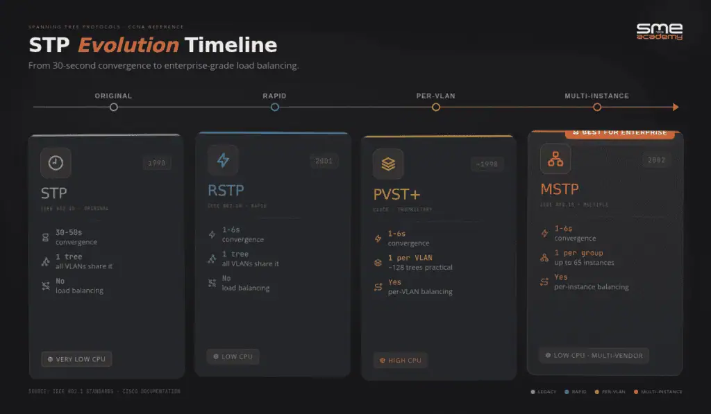
Classic STP (802.1D) runs one spanning tree for the entire network. Every VLAN shares the same logical topology. No load balancing. Convergence takes 30 to 50 seconds.
PVST+ (Cisco proprietary) fixed load balancing by running one STP instance per VLAN. You can make VLAN 10 use one uplink and VLAN 20 use another. That works well at small scale.
The problem: each instance consumes CPU and memory. At 20 VLANs, no issue. At 100 VLANs on a campus distribution switch, you’re running 100 concurrent STP computations. At 200+ VLANs in a data centre, PVST+ becomes a performance problem.
RSTP (802.1w) gave faster convergence (1 to 6 seconds) but didn’t fix the per-instance scaling issue. One tree still means no per-VLAN load balancing.
Rapid PVST+ combined the two – fast convergence with per-VLAN trees – but kept the same scaling problem.
MSTP splits the difference. It groups VLANs into instances, runs RSTP-speed convergence per instance, and advertises everything in a single BPDU. A 2024 performance evaluation study from ResearchGate confirmed MSTP wins on resource efficiency in multi-VLAN, large-scale deployments.
If you want a full breakdown of how PVST+ load balancing works before diving into MSTP, the per-VLAN spanning tree (PVST) guide covers the complete architecture.
Why MSTP was created
By the early 2000s, enterprise networks had hundreds of VLANs. PVST+ was running one STP instance for each of them. Every switch had to calculate, store, and transmit BPDUs for every single VLAN. That cooked CPUs on distribution and core switches.
The IEEE proposed a better idea in 802.1s: let engineers map all those VLANs into a small number of instances – maybe 2, 4, or 8 – while still keeping the ability to forward different VLANs down different physical paths.
MSTP was the answer. Cisco adopted it. Juniper adopted it. HPE Aruba adopted it. It’s now the standard way to run spanning tree on multi-vendor networks.
How Does MSTP Actually Work?
MSTP has four moving parts you need to understand: regions, instances, IST, and CIST. Get these four right and the rest is details.
1. MST Regions
An MST region is a group of switches that share three identical values:
| Attribute | Purpose |
|---|---|
| Region name | 32-byte string identifying the region |
| Revision number | 16-bit integer you increment when the VLAN map changes |
| VLAN-to-instance map | The table that says which VLANs belong to which instance |
If any one of those three is different between two switches, they’re in different regions. They’ll still talk to each other, but over the Common Spanning Tree (CST) using BPDUs that look like legacy 802.1D.
So the golden rule is: every switch in the same region must have identical MST configuration. No exceptions. Misconfigure one switch and it silently forms its own region – and your load balancing breaks.
2. MST Instances (MSTIs)
MSTP supports up to 65 instances per region (instances 0 through 64 on most platforms):
| Instance | Name | Purpose |
|---|---|---|
| Instance 0 | IST (Internal Spanning Tree) | Mandatory. Always exists. Unmapped VLANs go here. Handles communication outside the region. |
| Instances 1-64 | MSTI (MST Instance) | User-defined. Each covers a group of VLANs. Each can have its own root bridge for load balancing. |
Instance 0 is special. You can’t delete it. Any VLAN you don’t explicitly map to a user-defined instance automatically belongs to IST.
3. The Internal Spanning Tree (IST) – Instance 0
Instance 0 is special. It’s called the Internal Spanning Tree (IST) and it always exists. Every VLAN that you haven’t explicitly mapped to another instance lives in IST by default.
The IST is also the only instance that talks to the outside world. When your MST region needs to exchange spanning tree info with a non-MSTP switch or a different MST region, IST handles that conversation.
4. The Common and Internal Spanning Tree (CIST)
Two terms you’ll see in documentation:
- CIST (Common and Internal Spanning Tree) – the overall loop-free topology connecting all MST regions and non-MST domains across the entire network
- CST (Common Spanning Tree) – the external spanning tree that connects MST regions to each other
Think of it this way: CIST is the full picture. CST is the inter-region section. IST is the intra-region section. They all connect to form one loop-free network end to end.
5. The Master Port Role
MSTP adds one port role that RSTP doesn’t have: the Master port.
A Master port connects the MST region to the CIST root bridge located outside the region. It’s the region’s uplink to the rest of the network. The switch holding the Master port is the IST root for that region.
This role comes up in CCNP ENCOR exams and CCIE Enterprise labs. Know the difference between Master and Root port.
MSTP vs RSTP vs PVST+: Full Comparison Table
Here’s how all five major spanning tree variants stack up:
| Feature | STP (802.1D) | RSTP (802.1w) | PVST+ | Rapid PVST+ | MSTP (802.1s) |
|---|---|---|---|---|---|
| Standard | IEEE 802.1D | IEEE 802.1w | Cisco proprietary | Cisco proprietary | IEEE 802.1s |
| Convergence | 30-50 sec | 1-6 sec | 30-50 sec | 1-6 sec | 1-6 sec |
| STP Instances | 1 (all VLANs) | 1 (all VLANs) | 1 per VLAN | 1 per VLAN | Groups of VLANs |
| Port States | 5 | 3 | 5 | 3 | 3 (RSTP-based) |
| Load Balancing | No | No | Yes | Yes | Yes |
| Vendor Support | Universal | Universal | Cisco only | Cisco only | Universal (IEEE) |
| Resource Usage | Low | Low | Very high | Very high | Low-medium |
| Scalability | Poor | Poor | Poor | Poor | High |
| Cisco Default | No | No | Older IOS | Newer IOS XE | Must configure |
| BPDUs per trunk | 1 | 1 | 1 per VLAN | 1 per VLAN | 1 (all instances) |
| Best For | Legacy hardware | Medium networks | Small Cisco shops | Mid-size Cisco shops | Large enterprise, DC, multi-vendor |
The “BPDUs per trunk” row is where MSTP’s efficiency really shows. On a trunk carrying 200 VLANs, PVST+ sends 200 BPDUs every 2 seconds. MSTP sends 1.
How to Configure MSTP on Cisco IOS (CCNA/CCNP Example)
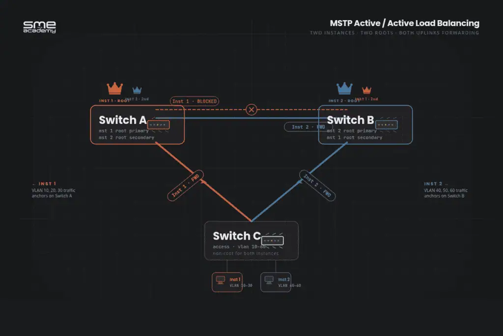
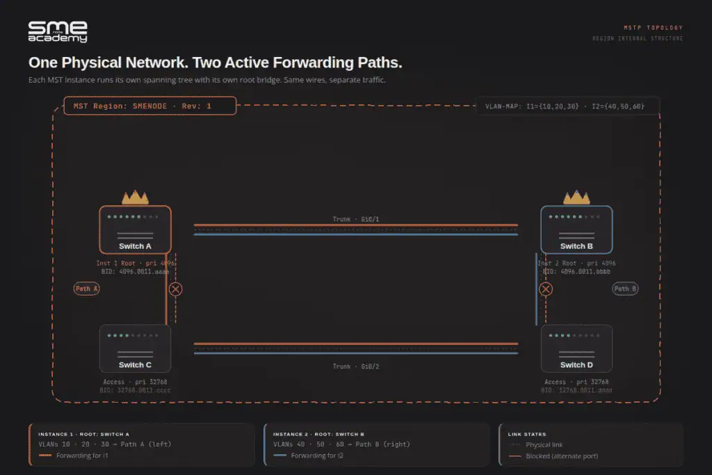
Let’s walk through a real MSTP configuration. We’ll set up two instances across three switches so that:
- Instance 1 carries VLANs 10, 20, 30 – root is Switch A
- Instance 2 carries VLANs 40, 50, 60 – root is Switch B
This gives you active/active load balancing.
Step 1: Enable MSTP globally
On every switch in the region:
Switch(config)# spanning-tree mode mstThis single command replaces PVST+ (the Cisco default) with MSTP.
Step 2: Enter MST configuration mode
Switch(config)# spanning-tree mst configuration
Switch(config-mst)# name SMENODE
Switch(config-mst)# revision 1
Switch(config-mst)# instance 1 vlan 10, 20, 30
Switch(config-mst)# instance 2 vlan 40, 50, 60
Switch(config-mst)# exit
The name, revision, and instance lines must be identical on every switch in the region. Copy and paste – don’t retype.
Step 3: Set root bridges
On Switch A (primary root for Instance 1, secondary for Instance 2):
SwitchA(config)# spanning-tree mst 1 root primary
SwitchA(config)# spanning-tree mst 2 root secondary
On Switch B (primary root for Instance 2, secondary for Instance 1):
SwitchB(config)# spanning-tree mst 2 root primary
SwitchB(config)# spanning-tree mst 1 root secondary
Now Instance 1 traffic will prefer paths through Switch A. Instance 2 traffic will prefer paths through Switch B. Congratulations – you’ve built real Layer 2 load balancing.
Step 4: Verify
Switch# show spanning-tree mst
Switch# show spanning-tree mst configuration
Switch# show spanning-tree mst interface Gig0/1
The first command shows the state of all instances. The second confirms your region settings. The third shows which instance is blocking on which port – handy for troubleshooting.
MSTP and PVST+ at the Boundary
This section is missing from most MSTP guides. Here’s what actually happens when an MST region connects to a PVST+ domain.
The MST region advertises only IST (instance 0) BPDUs externally. PVST+ switches can’t see inside the region – no MSTI visibility, no knowledge of instance 1 or instance 2. They just see one bridge.
The MST region appears as a single virtual switch in the PVST+ topology. The IST root bridge of the region is what PVST+ interacts with.
Practical implication during migration: If you’re converting a network from PVST+ to MSTP switch by switch, the boundary switches handle translation automatically. MSTP and PVST+ can coexist in the same network during migration. The boundary just needs to be configured correctly.
What to watch for: the IST bridge priority at the boundary affects how the external PVST+ topology sees the region. Set it deliberately rather than leaving it at the default 32768.
When to Use MSTP
MSTP is the right choice when:
- Your network has 50+ VLANs and redundant uplinks that need load balancing
- You’re in a data centre with multi-tenant VLAN separation and resource constraints
- You need a protocol that works across Cisco, Juniper, Arista, and HPE switches
- CPU utilisation on core switches is high due to PVST+ overhead
- You want load balancing without running one STP instance per VLAN
Stay with Rapid PVST+ when:
- You’re running a small-to-medium pure Cisco environment with under 50 VLANs
- Simplicity matters more than scalability
- Your team is comfortable with the existing config and there’s no performance problem
Use plain RSTP when:
- You need fast convergence in a multi-vendor environment
- Per-VLAN or per-instance load balancing isn’t needed
- The network is simple enough that a single tree works fine
MSTP isn’t a drop-in replacement for every network. It adds configuration complexity. A mismatched revision number or missed VLAN mapping will split a region silently – and that’s not always obvious until something stops forwarding.
Spanning tree controls your Layer 2 topology. Once that’s solid, understanding BGP vs OSPF is the Layer 3 equivalent decision every network engineer needs to make. For the full picture of where MSTP fits in a networking career, the network engineer roadmap for 2026 maps out certifications and skills in order.
Common MSTP Mistakes (and How to Avoid Them)
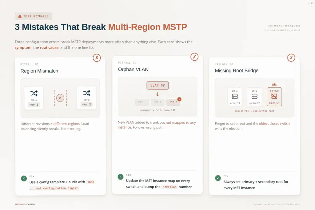
Three mistakes break MSTP deployments more often than anything else.
Mistake 1: Mismatched region configuration
One switch has revision 1. Another has revision 2. They’re now in different regions. Load balancing silently breaks and you won’t see an obvious error – just wrong port states.
Fix: keep region name, revision, and VLAN map in a config template. Paste it on every switch. Audit with show spanning-tree mst configuration digest.
Mistake 2: Forgetting to map new VLANs
You add VLAN 99 to the trunk. You don’t add it to any instance. VLAN 99 falls into Instance 0 (IST) and follows the IST’s path – which may not be what you wanted.
Fix: whenever you add a VLAN, update the MST instance map on every switch in the region and bump the revision number.
Mistake 3: Leaving one root unconfigured
You set Switch A as root for Instance 1. You forget to set a root for Instance 2. Now Instance 2 elects whatever switch has the lowest MAC address – usually your oldest access switch in the wiring closet. Ugly.
Fix: always explicitly set a primary and secondary root bridge for every instance you create.
MSTP Interview Questions: CCNP ENCOR Level
These questions appear in CCNP ENCOR interviews and written exams. MSTP is one of the core switching topics in the top Cisco certifications for salary growth. If you’re still working on CCNA certification, focus on STP and PVST+ first – MSTP is the next step up.
Q: What problem does MSTP solve that RSTP doesn’t?
RSTP creates one logical topology for all VLANs. No per-group load balancing. MSTP groups VLANs into instances, allowing different forwarding paths per instance – load balancing at scale with far less overhead than PVST+.
Q: What are the three parameters that define an MST region?
Region name, revision number, and the VLAN-to-instance mapping table. All three must be identical on every switch in the region.
Q: What is IST and what happens to unmapped VLANs?
IST is Instance 0. It’s mandatory and always exists. Any VLAN not explicitly mapped to a user-defined instance defaults to IST. IST also handles communication with external switches outside the region.
Q: What is the Master port role in MSTP?
The Master port connects the MST region to the CIST root bridge outside the region. The switch holding the Master port is the IST root for the region. This role doesn’t exist in RSTP.
Q: How does MSTP interact with a PVST+ domain at the boundary?
The MST region appears as a single bridge to the PVST+ domain. Only IST BPDUs are sent externally. PVST+ switches have no visibility into individual switches or user-defined instances inside the region.
Q: Why is MSTP more efficient on trunk ports than PVST+?
PVST+ sends one BPDU per VLAN per hello interval. On a trunk with 200 VLANs, that’s 200 BPDUs every 2 seconds. MSTP sends a single BPDU carrying data for all instances, regardless of VLAN count.
Q: Can MSTP and PVST+ coexist in the same network?
Yes. The MST boundary handles translation. MSTP regions and PVST+ domains interoperate. The region appears as one bridge to the PVST+ domain.
What’s New in 802.1Q-2022?
The latest 802.1Q revision tightens how MSTP interacts with newer protocols like Shortest Path Bridging (SPB) and EVPN. If you work in a data centre, you’re probably moving away from MSTP at the fabric layer toward EVPN-VXLAN – but MSTP still rules the campus access layer and most brownfield enterprise networks. Expect it to be on CCNA and CCNP exams through 2027 and beyond.
Want the career path that goes with these skills? Check our guide on how to become a network engineer in 2026 for the certification roadmap and salary benchmarks.
Frequently Asked Questions
What does MSTP stand for?
MSTP stands for Multiple Spanning Tree Protocol. It’s defined in IEEE 802.1s and merged into IEEE 802.1Q-2005. MSTP maps many VLANs to a smaller number of spanning tree instances, giving you per-instance load balancing with low CPU overhead.
Is MSTP the same as IEEE 802.1s?
Yes. MSTP was originally defined in IEEE 802.1s (2002) and later incorporated into the broader IEEE 802.1Q-2014 consolidated standard. Both terms refer to the same protocol.
How many MST instances can you configure?
You can configure up to 65 MST instances per region (Instance 0 to 64). In practice, most networks use 2 to 4 instances. Instance 0 is the Internal Spanning Tree (IST) and always exists.
How is MSTP different from RSTP?
RSTP (802.1w) runs a single spanning tree for all VLANs. No per-group load balancing. MSTP runs multiple instances, each covering a group of VLANs, each capable of using a different root bridge and forwarding path. Both use the same RSTP convergence mechanics at 1 to 6 seconds.
What happens to VLANs not mapped to an MSTP instance?
Any VLAN not explicitly mapped to a user-defined instance (MSTI 1 through 64) automatically belongs to IST (Instance 0). They participate in spanning tree – they just don’t have a dedicated instance. If IST’s root bridge isn’t ideal for those VLANs, that’s a forwarding problem worth addressing.
How many MST instances can a Cisco switch support?
Most Cisco platforms support 65 instances per region: Instance 0 (IST) plus instances 1 through 64 (user-defined MSTIs). The IEEE 802.1s standard defines instance IDs from 1 to 4094, but actual hardware support varies by platform.
Can MSTP and PVST+ coexist in the same network?
Yes. The MST region boundary handles translation automatically. Switches inside the region run MSTP. Switches outside run PVST+. The region appears as one bridge to the PVST+ domain. This coexistence is what makes phased MSTP migrations practical.
How many MST instances can a Cisco switch support?
Most Cisco platforms support 65 instances per region: Instance 0 (IST) plus instances 1 through 64 (user-defined MSTIs). The IEEE 802.1s standard defines instance IDs from 1 to 4094, but actual hardware support varies by platform.
What to Study Next
MSTP sits squarely in CCNP ENCOR and CCIE Enterprise territory. If you’re working towards either certification, spanning tree variants are mandatory knowledge – in the exam and in production.
Build the foundation first:
- Per-VLAN spanning tree (PVST) explained – the load balancing model MSTP improves on
- CCNA certification guide – STP and PVST+ are CCNA exam topics before you get to MSTP
- Network engineer career roadmap for 2026 – where MSTP fits in the cert path
Go deeper on Cisco certs:
- Top 5 Cisco certifications for salary growth – CCNP ENCOR and CCIE Enterprise both test MSTP
Expand beyond Layer 2:
- BGP vs OSPF: when to use which routing protocol – the Layer 3 equivalent decision to spanning tree mode selection
Courses and study materials:
- CCNA training course – covers STP, RSTP, and PVST+ with switching labs
- CCIE Enterprise course – full MSTP labs including mismatched region scenarios and boundary behaviour
- CCNA lab workbook at SMEnode Labs – step-by-step spanning tree configuration and troubleshooting exercises